| Zalman Reserator 1 Plus Water Cooling System - Page 4 of 6 |
Installation:
This brings us to the next part, installation. Installing the water cooling system began by assembling the entire system outside of my computer first in order to assure there were no leaks. Putting the fittings together was really reassuring and gave the feeling of a sturdy well built device. After installing one of the hose clamps I realized that I needed to shorten a piece of hose, so I attempted to pull the hose back off, this proved impossible and I ended up having to cut the tubing from the clamp because it was sealed so well.
Before I go any further I would like to say that once all of the air bubbles have been pushed out of the system the cooler is virtually noise free. Actually it was so quiet that I wasnt sure if it was running at all except for the visual from the flow indicator vibrating inside its chamber.
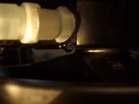
After running the cooler for about 24 hours outside the computer I did a leak check to ensure all was well. None of the internal parts showed any signs of leakage, I did however find a ring of water just under the main Reserator stand. After further inspection I found the leak was coming from the outlet side of the Reserator just under the fitting. One half turn with a wrench and the leak completely stopped. The image below shows the water droplet formed under the fitting (sorry for the poor image quality).
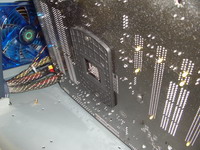
24 hours later, no signs of leaks anywhere this time. Lets put this bad boy together. Starting with the CPU block, assembly went rather smooth; the first step involved placing the correct back plate behind the CPU. For this application the 939 setup is used. Be sure to use the provided washers to ensure no grounding of important components. The left image shows the back plate installed behind the motherboard, the image on the right shows the screw tightened firmly to the plate.
 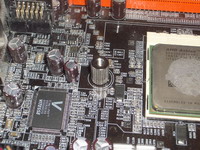
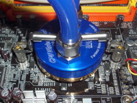
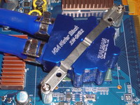
After a fresh application of the provided thermal paste we are ready to clamp down the CPU block. An extra set of hands would have been helpful here but werent available at the time. On my second try this went rather well, the main problem I had was lining up the block while trying to tighten the pegs, although I dont think this would have been such a big deal if I hadnt already connected all of the tubing. Here we see the finished product.
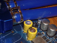
Same story with the VGA blocks, an assistant would have come in handy. Here we see the cooler being placed on a 6600GT Rosewill video card (left). Just a side note, the hose does rub one of the capacitors, not a lot of stress was placed on the capacitor but just be aware that this is happening (right).
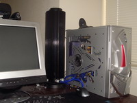
The rest of the installation is really self explanatory and no snags were found. The next few images show the final product ready for action along with my mess of wiring.
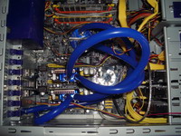 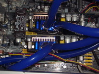
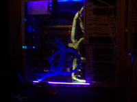
Towering over my case we see the cooler in action below left. The image on the right shows the tubing reacting to a CCFL black light.
Please read on to the next page for more... Next
Page 1 | Page 2 | Page 3 | Page 4 | Page 5 | Page 6 | Home | Forum | Content Index
|
|
|
|


