| Serener GS-L01 Fanless Mini-ITX Case - Page 3 of 6 |
The Heatpipe Cooler:
The most interesting accessory is the aluminum heatpipe cooler, and it deserves its own chapter. The block shown below is intended to mount to both the CPU and northbridge, and draw heat out to the case's side wall.
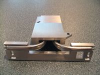 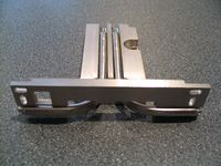
As seen in the images above, the closer flat surface mates with the CPU, and the more distant surface is for the northbridge. Two spring-loaded plastic pins are intended to hold the cooler to the motherboard. Two heatpipes then convey the heat to an aluminum strip that is secured to the case with two screws.
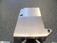
The image below provides a close up of the heatsink's base to show that although quite flat, the machining marks indicate that it isn't as smooth as possible.
Internal Features:
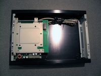
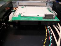
The view below is what you have with the top cover removed. In the lower left corner is the DC power board, and just above this is a special PCB/bracket designed to support both the hard drive and optical drive. The large open area to the right is where the motherboard mounts.
The below left image provides an end view of the drive mounting PCB/bracket. The optical drive mounts on top, and the hard drive is attached to the bottom of the PCB in an upside orientation. This bracket eliminates the need for any power or data cable to these drives, as all connections are made through sockets on the PCB. Quite an ingenious design, and one that makes installation easier and neater.
 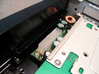
The above right image provides a quick look at the exposed components of the DC power board. A typical 20-pin ATX connector is located at one end, and the included cable can be used with either end plugged into it.
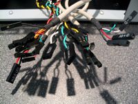
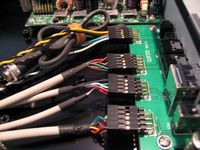
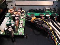
The below left image shows all of the wires needed to install the front panel connections. All of the connections are well labeled, and the USB, Firewire, and audio wires are bundled into heavy duty cables. The below right image also shows the power cable, which needs to be routed to the hole at the back of the case and secured with the included nut and lock washer.
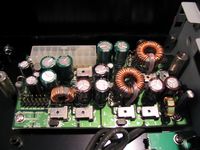
The images below provide a closer look at the 90W DC power board. In addition to the 20-pin ATX connection, the other necessary feature is the 14-pin connection located in the lower left corner of the below right image. The PCB/bracket that holds the optical drive and hard drive plugs in here, and provides power through a direct connection.
Please read on to the next page for more... Next
Page 1 | Page 2 | Page 3 | Page 4 | Page 5 | Page 6 | Home | Forum | Review Index
|
|
|
|


