| Titan TWC-A04 Water Cooling System - Page 3 of 5 |
Before installation, lets take a look at the published specifications of the two fans and the water pump...
Fan and Pump Specifications / Features (summarized from the Titan website):
Main Cooling System:
Outline Dimension - 149.5*42.7*85.5mm
Rated Voltage - DC 12V
Rated Current - LO:0.11A - HI:0.23A
Power Consumption - LO:1.32W - HI:2.76W
Rated Speed - LO:1300+/-10%RPM - HI:2900+/-10%RPM
Max. Airflow - LO:24.7CFM - HI:52.6CFM
Noise Level - LO:23dBA - HI:34dBA
No.of Pole - 4 Pole
Rotation Direction - Counter-Clockwise
Water Pump Motor:
Rated Voltage - DC 5V
Rated Current In Water - 0.24A
Power Consumption - 1.2W
Rated Speed In Water - 1600+/-10%RPM
High In Water - 500MM
No.of Pole - 4 Pole
Rotation Direction - Counter-Clockwise
Secondary Radiator:
Outline Dimension - 94.7*86.47*76mm
Rated Voltage - DC 12V
Rated Current - LO:0.1A - HI:0.135A
Power Consumption - LO:1.2W - HI:1.62W
Rated Speed - LO:2300+/-10%RPM - HI:2800+/-10%RPM
Max. Airflow - LO:30.06CFM - HI:35.48CFM
Max.Static Pressure - LO:2.83mmH2O - HI:3.61mmH2O
Noise Level - LO:<21dBA - HI:<27dBA
No.of Pole - 4 Pole
Rotation Direction - Counter-Clockwise
The published specifications all tell me that this setup is meant for silence, and not necessarily high performance (if you equate high air/water flow to performance). Now that all the components have been given a once over, and the features are understood, lets put this thing together...
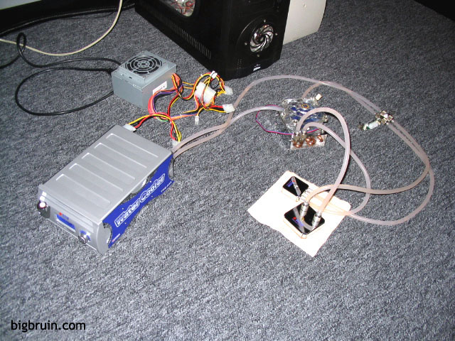
Whenever a water cooling setup is to be installed, it is of utmost importance to first conduct a leak test, no matter what. As detailed in the below left image, I assembled the entire circuit as it would be installed in my case, filled it with water/antifreeze, and let it run off a test power supply. As recommended in the manual, the process flows in this fashion: Main Cooling System -> PCI Bracket -> CPU Block -> Secondary Radiator -> GPU Block -> PCI Bracket -> Main Cooling System. The system was then allowed to run for 3 days as pictured, and after that period I was very happy to see zero leakage. One thing I was not happy to see was related to the air in the system. The main concern was a few 'air locks' I witnessed, where sections of tubing would develop several inches void of liquid, and the pump was apparently incapable of providing enough pressure to overcome this. Tapping the lines, shaking the components, and elevating the reservoir did little to help, and it came down to a waiting game as the system slowly worked the air out. During this process, the pump gurgled as air passed through regularly, but once the roughly four hours had passed, it ran silently for the balance of the leak test.
 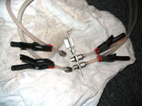
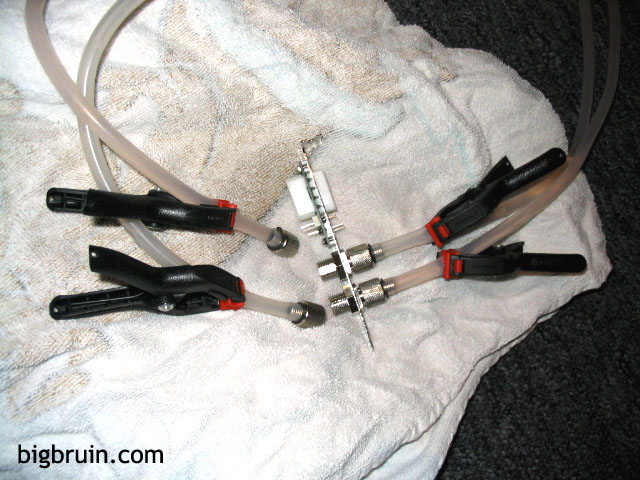
Not looking forward to repeating the extensive air bleeding process, I decided not to drain the system before moving it into my case. As pictured in the above right image, I used a few small Craftsman clamps to pinch the lines shut on either side of the PCI bracket. It worked well, with just a few drops of liquid being lost, and seemed to greatly simplify the transfer into the case. Unfortunately, this wasn't the case (more on this later).
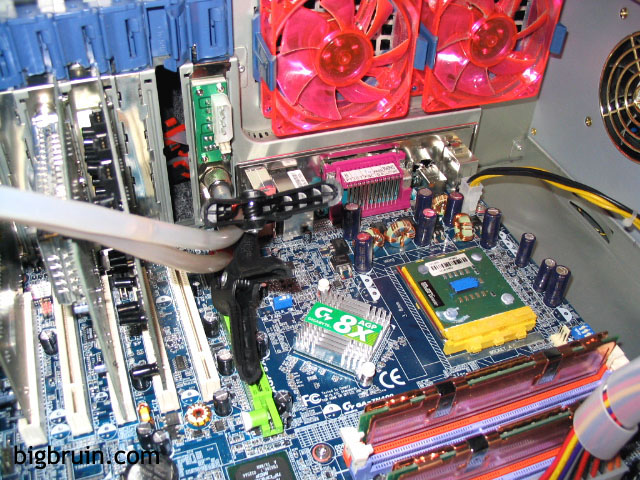
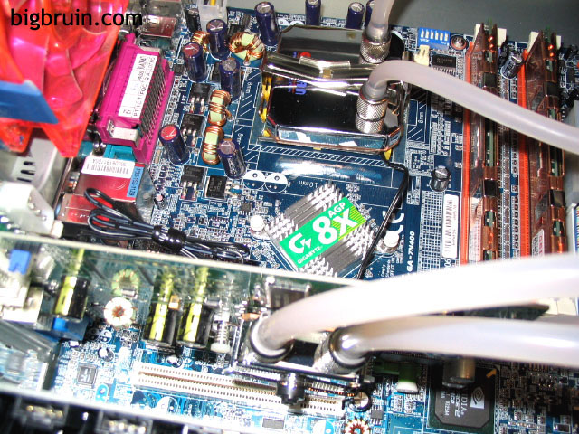
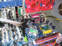
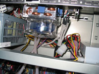
The below left image shows the tubing reconnected to the PCI bracket, once installed into the case (clamps still intact). On the right-hand side of this image you can see the unique blue thermal paste applied to the XP2800+ CPU to be used in testing.
 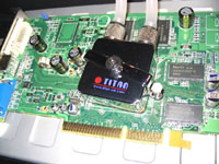
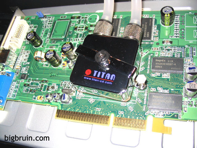
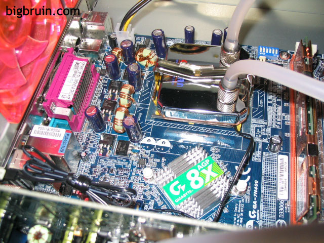
The above right image shows the water block installed onto the Radeon 9600 to be used during testing. Installation was simple, and the fit was snug and secure. One downside experienced with the location of the water connections on this block is the interference it would cause with ramsinks. As you can see, it would not be possible to use memory cooling on the two chips directly below the two connections.
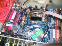
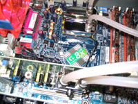
The two images below provide a glimpse at the CPU block installed. Installation was easy, perhaps easier than any heatsink I had installed before. The clip first attaches to three lugs on one side, and a small block on the top of the water block fits into a notch on the clip to align everything perfectly. Slight pressure with a screwdriver is all that is required to secure the other side, and a tight mounting is achieved.
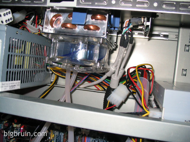
I decided to mount the secondary radiator inside my case, using a top exhaust vent which had previously gone unused. The holes in the vent may restrict flow a bit, but the low flow of the radiator's fan shouldn't be overly impacted.
Please read on to the next page for more... Next
Page 1 | Page 2 | Page 3 | Page 4 | Page 5 | Home | Forum | Review Index
|
|
|
|