The Basics (continued):
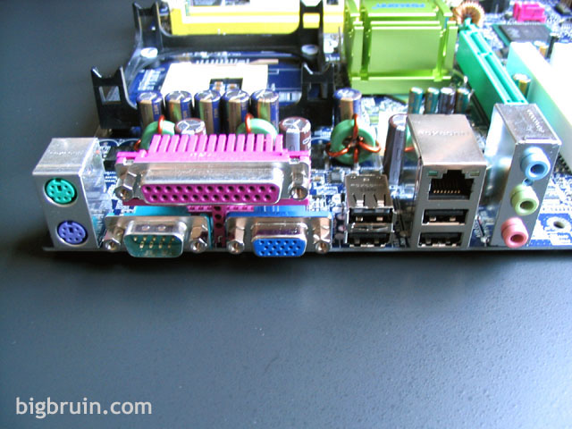
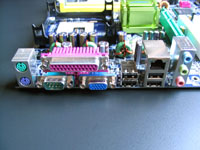
The image below shows the external connections available on the back of the board, which include; PS/2 mouse and keyboard, Serial port, Parallel port, 15-pin VGA port, (4) USB 2.0 connections, 10/100 LAN port (with LED activity indicators), and connections for the 5.1 channel stereo sound. I was considering this motherboard for use in an HTPC application, and planned on taking advantage of the onboard audio and video to simplify the configuration. I was surprised to see only the 15-pin VGA connection for video, as an s-video (or even composite) connection would have been nice for use with a television.
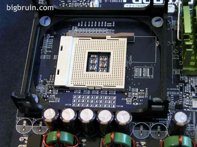
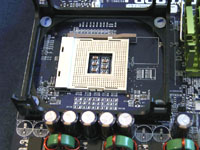
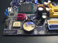
The CPU socket is shown close up below, and it is obviously positioned as close to the edge of the board as possible. A few capacitors and other features reside very close to the mounting bracket, but I experienced no issues with installation using a few different air coolers, as well as an Innovatek water cooling solution.
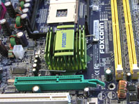
The northbridge is passively cooled via the metallic green heatsink shown below. Other features visible in this image are the CPU fan header just to the right of the CPU socket, and the 4-pin auxiliary power connector located just to the left of the cpu socket. This 4-pin connector is one of the few items not located near the edge of the board, but it is key to have the power delivered right where it is needed, so this positioning is not uncommon.
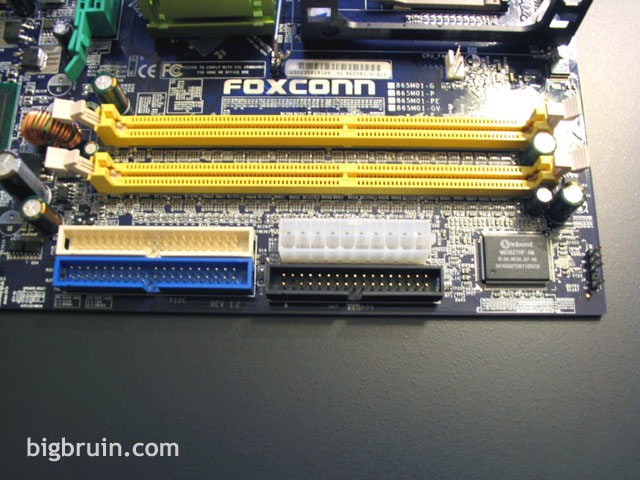
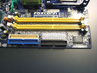
The two DDR slots capable of dual channel operation at 400 MHz DDR (and beyond via overclocking) are seen below in bright yellow. Other features conveniently located near this edge of the board include the two IDE connectors, the floppy connector, and the 20-pin ATX power connector.
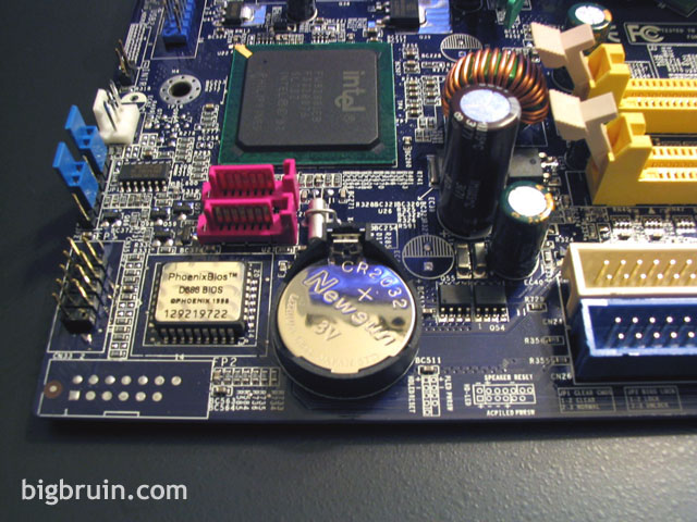
The lower corner of the board is shown below, and key features include the CMOS battery, the southbridge chip, two Serial ATA connectors, front panel connectors, and one of two 3-pin fan headers found on the board. Continuing the theme of locating items near the edge of the board, several connections are found in this area that will make installation and wire management a snap. I even liked the jumpers provided (two blue ones show below), as they were easy to grab a hold of.
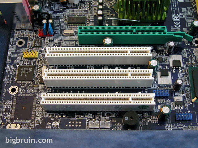
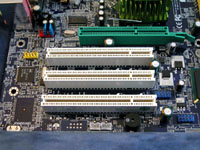
The three PCI and one AGP slot are shown below, as well as blank spot on the board where a Firewire connection would be located. The AGP slot has a unique retention mechanism which simply implements a clip on a piece of flexible plastic. It worked well for me, but as with most designs for this device I had a tough time getting my finger in there to release the catch when I wanted to remove the AGP card. The black cylinder at the bottom of the image is a built in pc speaker, a nice touch which eliminates the 4 pins usually required in the front panel connections.
Please read on to the next page for more... Next
Page 1 | Page 2 | Page 3 | Page 4 | Page 5 | Page 6 | Page 7
Home | Forum | Review Index
|
|