The Basics:
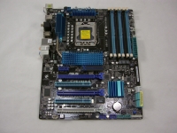
On to a look at the physical layout of the ASUS P6X58D-E. The image below shows an overview of the board, and the subsequent images will zoom in for a closer look at different locations on the board. The PCB is colored black, with blue accents in the form of heatsinks and slots for memory and expansion cards.
The interesting layout of expansion slots is shown in the image below. From top to bottom there is a PCI Express 1x slot, then an alternating array of PCI Express x16 slots (three total) and PCI slots (two total). If you plan to use dual graphics cards on this motherboard you might have to forget about using any PCI cards, as they will surely be blocked by the video card's coolers. The two blue colored PCI Express x16 slots are capable of a maximum of x16 performance, so they are definitely the ones you want to use for video cards. The white slot may be x16 physically, but it is only capable of a maximum of x8 performance.
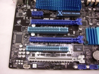
While there is plenty to see in the image above, one other key feature is the onboard power button. This is a great item for troubleshooting, or for test builds outside of a traditional case. When the system is powered up, or simply receiving power but not on, the button glows red to make it easy to locate.
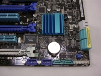
Traveling a bit to the right of the previous image we arrive at the items shown in the image below. The asymmetrical blue heatsink is cooling the Intel ICH10R chip, which among other things controls the six blue SATA headers found in this area. While these SATA ports are of the 3.0 Gbps variety, the two gray SATA ports we see are capable of 6.0 Gbps performance thanks to a Marvell controller. We also see a handful of USB 2.0 headers, and a bank of front panel connectors ready to accept the Q-Connector blocks.
Heading north from our previous location we find the area of the board that is populated by memory slots. In particular, this board has six 240-pin DDR3 slots rated to accept 1GB, 2GB, or 4GB modules rated anywhere from 1066MHz up to 2000MHz. The system is capable of triple channel operation, which requires 3, 4 or 6 modules to be installed. If you are running with a traditional triple channel setup of three modules, you need to use the blue slots, and save the black slots for when/if you ever add more modules.
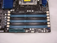
Another feature of interest in this area is a small button located to the right of the two fan headers shown in the image above. Pressing the MemOK! button allows the system to analyze the modules and adjust their settings to overcome incompatibility. If the system fails to boot due to memory issues, a small light in this area will illuminate, indicating that you should press and hold the MemOK! button until it has found the settings that will allow the memory to function with the system. The basic steps of MemOK! are that it will attempt to relax timings, then attempt to lower DRAM frequency, then attempt voltage cycling, and finally it will attempt a mix of these options.


