If the installation of the
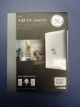
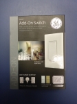
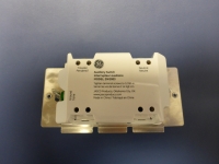
first in a series of Jasco Z-Wave devices didn’t intimidate you then this one might. Many of your lights in your home will be controlled by more than one switch; these are 3-way and 4-way circuits. In order to control these you need to get one or more of the GE Add On Switches. Here we have the Z-Wave GE 12728 In Wall Add On Switch (Toggle style) and the GE 12723 Add On Switch (Paddle style). Both are UL listed for use with 120V 60Hz circuits, mounted indoors with a temperature range of 32-104F (0-40C). They are also packed in the same type of box described earlier but as mentioned these have a gray stripe to indicate they are platform independent, so they can be used with ZigBee and Bluetooth as well.

 Packaging and Accessories:
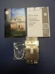
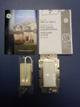
The two packages and their contents are shown below, and are basically identical with one exception; the toggle switch only comes in white with no almond replacement.
 The Basics:
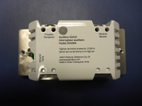
The switch layout between the two is basically the same; there is a terminal for your traveler and one for your neutral. Again the terminals are identified very clearly.
 Initial Setup:
Again, you do all of this at your own risk, this can be dangerous to you personally and your property. Think about what you are doing and be careful! If in doubt hire a licensed electrician.
Initial Setup:
Again, you do all of this at your own risk, this can be dangerous to you personally and your property. Think about what you are doing and be careful! If in doubt hire a licensed electrician.
This is where things can get very confusing since the instruction set only provides a schematic for a 3-way circuit even though the box mentions you can have up to four add-on switches. And again they gloss over how you determine which wire is the hot, nor do they even mention a multimeter is needed to confirm this.
As you can see below a typical 4-way circuit has three switches. The two at either end are 3-way switches and have three terminals each. The switch in the center is a 4-way and has four terminals. So if your current lighting circuit is working you know the power feed is coming in to one of these 3-way switches and should be the black wire in one of the #14/2 bundles not the bundle that has the red wire. Again the next step is dangerous; energize the circuit but make sure the light is out. Measure the voltage at the switch terminal that has the black wire from the #14/2 wire. One should be hot the other should be dead. The box that has the 120V is your feed from the panel, mark it as such and disconnect the power to the circuit. If your circuit has more than three switches there will be additional 4-way switches in the middle, so the above still holds true. Find the 3-ways, one has the load the other is the 120V source.

Since the GE Smart Switch has four terminals the average DIYer will likely try to install this in the middle gang box. The truth is you can install it any of the boxes providing you wire the rest of the circuit correctly but Jasco’s recommended position is the gang box which is fed directly from the breaker so we will discuss that installation. This circuit is fundamentally different than a traditional 3 or 4-way circuit because the Add On switches do not pass the power through them to the load. The best way to visualize this is to ignore the Add On Switches for now. Go to the gang box where you found the feed from your panel and start to install your primary switch, something like the Z-Wave GE 12724 In Wall Smart Dimmer Switch covered previously. Connect the white jumper wire to the neutral terminal and terminate the other end in the white bundle in your gang box. Next take the black wire from the #14/3 wire and attach that to your load terminal and the red wire from that bundle to the traveler. Install the hot wire you found earlier to the line terminal and don’t forget to attach your ground wire. Next, go to the other boxes and jumper the black wires together. This essentially by-passes the Add On switches from the load. Now in the other boxes attach the white jumper to each neutral terminal and to the bundle in the gang box. Attach the traveler(s) to the terminal labeled traveler and of course make sure the switches are attached to a good ground. At this point you should close up the gang boxes and restore power to the circuit. If done correctly the blue LED on the front of the primary switch should be illuminated, providing light is off. Then go to each switch and try actuating the switch leaving the light in a different state before proceeding to the next switch. If the light always works regardless of other switch inputs then you are set to proceed to pairing this with your hub.
The pairing process will be identical to what was described earlier; even though you have multiple switches installed only the master GE Smart Dimmer has Z-Wave capabilities. The GE Add On switches simply communicate with the master by sending a pulse signal over the connected wires.


