|
 Posted: July 21, 2003 Posted: July 21, 2003
Author: Jason Kohrs
Manufacturer: Thermalright
Source: Thermalright
Installation:
Following the basic installation guidelines provided on the Thermalright website, I installed the SLK-800U on my Asus A7N8X Socket 462 motherboard. Although a much more involved process than installing your typical clip-on heatsink, it is not difficult (if you bother to read the directions). I wont cover every step in great detail, since the link I provided above already does, but I will cover the basics of the installation, highlighting the key steps.
The biggest step in the installation, which many people might not appreciate, is that you must remove your motherboard from the case, so that you can install the retention system, pictured in the below left image. Its a black piece of steel with a foam pad that presses against the backside of your motherboard, and a transparent sheet of plastic sandwiched in between to prevent electrical shorts. As pictured in the below right image, you line it up with the holes in your motherboard, and thread the mounting standoffs into it from the top side.
 
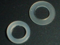 Before you actually thread the standoffs into the retention system, you need to determine what washers are appropriate for use on your board. AMD boards come with holes in two standard diameters, 6mm and 4.2mm. If your board has holes that are 6mm in diameter, you will use both washers, with the smaller washer acting as a bushing inside the hole, and the larger washer being sandwiched between the board and the standoff. If you have a board with 4.2mm holes, you only use the larger washer, which is what was required for my installation. Before you actually thread the standoffs into the retention system, you need to determine what washers are appropriate for use on your board. AMD boards come with holes in two standard diameters, 6mm and 4.2mm. If your board has holes that are 6mm in diameter, you will use both washers, with the smaller washer acting as a bushing inside the hole, and the larger washer being sandwiched between the board and the standoff. If you have a board with 4.2mm holes, you only use the larger washer, which is what was required for my installation.
As pictured in the images below, the standoffs were placed into the holes on the motherboard and threaded into the retention system. The standoffs were tightened slightly at alternate corners (to ensure an even mounting), until all four were secure. In the below right image, the large washer is visible between the standoff and the motherboard...
 
At this point, a razor thin coating of the included thermal paste was applied to the core of my cpu, and the SLK-800U was put into place with the holes in the black base aligned with the holes in the standoffs. One metal washer was then placed on top of each hole in the black base of the SLK-800U, and the spring-mounted screws were screwed in just enough so that they would grab a few threads. The four screws were then tightened slightly at alternate corners (again, to ensure an even mounting), until all four were fully secured. There is no need for concern about crushing your core, as the design of the SLK-800U is such that if you follow the directions, you will have a perfect fit, and all four screws will be fully tightened. The two images below show details of the spring-mounted screws fully engaged in the standoffs...
 
With the SLK-800U full secured, the motherboard is now ready to be returned to its case, and have a fan fitted to the heatsink. Although not detailed in the installation instructions, and perhaps not necessary, I used the included black foam strips as a vibration isolator between my fan of choice (the Thermaltake Smart Fan II), and the top of the SLK-800U. As pictured in the below left image, you can see the two black strips placed so that the edge of the fan will sit on them. Then, with the proper retaining wire selected, and inserted into the appropriate holes in the side of the heatsink, the fan is held securely in place. I was skeptical that these retaining wires would do the trick, but the pressure they exert on the fan is substantial, and the elbows of the retaining wires sit in the circular depressions on the face of the fan, providing even greater security (see below right image for more detail)...
 
Please read on to page three for the testing and conclusion... Next
Page 1 | Page 2 | Page 3 | Review Index
|


