|
 Posted: May 22, 2003 Posted: May 22, 2003
Author: Jason Kohrs
Manufacturer: Maxtop
Source: Maxtop
 Internal Features: Internal Features:
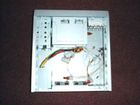
With the top cover removed you can start to investigate the internal features... Going clockwise around the case starting in the upper left hand corner of the image on the right you have: (2) internal 3.5” drive bays, a removable 5.25” and 3.5” drive bay rack, the wiring to the case front features,the 80mm intake fan with 4-pin pass-through power lead, two 60mm exhaust fans with 4-pin pass-through power leads, and the 200 Watt Micro-ATX power supply.
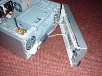 As mentioned on the first page, depressing the spring-loaded panel on the left hand side of the case creates a handle to remove the front face without tools. By gently pulling forward on the handle the face pops off and can be placed off to the side while you work. Removing the front face is necessary for installing any of the drives, as well as coming in handy for installing the motherboard, as it will allow you to remove the drive bays and free up some space. While you have the front panel removed you might as well take a look at the electronic connections... As mentioned on the first page, depressing the spring-loaded panel on the left hand side of the case creates a handle to remove the front face without tools. By gently pulling forward on the handle the face pops off and can be placed off to the side while you work. Removing the front face is necessary for installing any of the drives, as well as coming in handy for installing the motherboard, as it will allow you to remove the drive bays and free up some space. While you have the front panel removed you might as well take a look at the electronic connections...
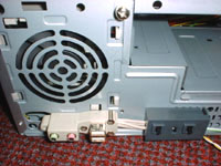 As pictured on the right, the electrical connections aren’t your typical generic items held in by hot-melt glue. The media connections are integrated into the beige housing on the left which is screwed into the case’s frame and the power/reset switches are integrated into the sturdy looking grey housing on the right. The 80mm intake fan can also be seen in this picture, mounted to the front of the case with a tool-less mounting device. Again, these are subtle touches that may get overlooked by the average consumer, but I appreciate the quality of features such as these. As pictured on the right, the electrical connections aren’t your typical generic items held in by hot-melt glue. The media connections are integrated into the beige housing on the left which is screwed into the case’s frame and the power/reset switches are integrated into the sturdy looking grey housing on the right. The 80mm intake fan can also be seen in this picture, mounted to the front of the case with a tool-less mounting device. Again, these are subtle touches that may get overlooked by the average consumer, but I appreciate the quality of features such as these.
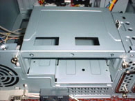 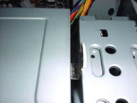 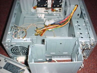
The three images above give the step by step process for removing the rack that supports the externally accessible 5.25” and 3.5” drive bays. The rack is secured by two thumb screws pictured in the image on the left. By removing these, and depressing the white lever on the right hand side of the rack (detailed in the center image), the drive rack will then hinge forward. As pictured in the image on the right, the drive rack is still attached to the case, but provides unobstructed access to the motherboard area. You can leave the rack attached as pictured, or you can remove it completely by lifting up and pulling away from the case.
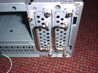 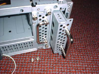
The two images above show the internal 3.5” drive bays. Each drive bay is secured by 2 thumb screws and features a hinged handle for easy installation of your hard drives. This design is obviously a cross-over from Maxtop’s work on rackmount enclosures, and I like it. Just another small touch that has been included in the CSX-001 that will really contributes to the overall satisfaction of its users.
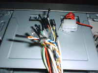 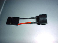
The two images above detail the electrical connections to be found inside the case. The left image shows the numerous front panel connectors that will wind up being attached to your motherboard, as well as the 4-pin power connector for the 80mm intake fan. The imaage on the right is Maxtop’s unique solution for the pc speaker. Instead of mounting the standard pc speaker to the inside of the case somewhere, they have provided this small speaker wired directly to the motherboard connection. I have never seen one like this before, and I wouldn’t mind having something like this in every case. It functions the same as the typical pc speaker but leaves the internal surfaces of your case uncluttered and available for other uses (water cooling components, case-mods, etc...).
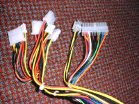 The image on the right shows the various power leads coming from the 200 Watt power supply. You are supplied with (4) standard 4-pin connectors for drives/fans, (2) mini 4-pin connectors for floppies, (1) 4-pin 12V connector (P4 style), and the 20 pin ATX power connector. The leads have an overall length of 14” from the power supply to the first connector, which is much shorter than your standard power supply, but more than enough to provide power to all of the components in a case of this size. If it weren’t for the pass-through power connections on the fans, 4 of these 4-pin power connections wouldn’t be enough, but they obviously figured that out. The image on the right shows the various power leads coming from the 200 Watt power supply. You are supplied with (4) standard 4-pin connectors for drives/fans, (2) mini 4-pin connectors for floppies, (1) 4-pin 12V connector (P4 style), and the 20 pin ATX power connector. The leads have an overall length of 14” from the power supply to the first connector, which is much shorter than your standard power supply, but more than enough to provide power to all of the components in a case of this size. If it weren’t for the pass-through power connections on the fans, 4 of these 4-pin power connections wouldn’t be enough, but they obviously figured that out.
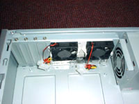 Taking a look at the back of the case, you see the two 60mm exhaust fans. Just like the 80mm fan on the front of the case, each of these fans is equipped with a pass-through power connector, and mounts to the case with a tool-less mounting device. The leads on these fans are a little short, which could make wire management an issue. If the power connectors are all being used on drives, these leads will have to run straight over the top of the motherboard in order to reach, and may interfere with items such as a cpu fan. Also pictured are the 4 pci slots with matching covers screwed into place Taking a look at the back of the case, you see the two 60mm exhaust fans. Just like the 80mm fan on the front of the case, each of these fans is equipped with a pass-through power connector, and mounts to the case with a tool-less mounting device. The leads on these fans are a little short, which could make wire management an issue. If the power connectors are all being used on drives, these leads will have to run straight over the top of the motherboard in order to reach, and may interfere with items such as a cpu fan. Also pictured are the 4 pci slots with matching covers screwed into place
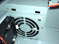 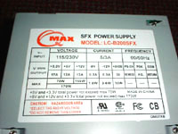
As pictured in the above left image, the power supply mounts into the corner of the case with a low profile 80mm fan drawing air into the unit. In order to view the power supply’s rated specifications you must remove it from the case, at which point you can see the sticker as pictured on the above right. This unit, and any other Micro-ATX power supply for that matter, have low power outputs relative to their full size equivalents. You’re only supposed to be powering your motherboard, a limited number of drives, and a few fans. Without overloading a psu such as this with too many peripherals there should be plenty of power to maintain a stable, somewhat basic system.
Now that we’ve taken a look at the basic internal and external features, please read on to page 3 for the Installation and Conclusion... Next
Page 1 | Page 2 | Page 3
|